Pictures
Here is a collection of photos that I have taken during the project. A click on any picture will show a larger view of that picture.
CPU-card
|
|
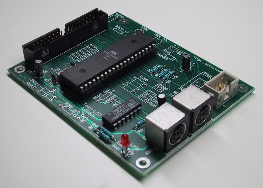
This picture shows the CPU-card (the new "general" PCB) with the Atmel AT90S8515 CPU, the 74HC4066, the PC and keyboard connectors, the 34-pin IDC connector for the connector-card and the 6-pin IDC connector that is used for downloading of software to the CPU. |
 |
Here is the same CPU-card shown directly from above. |
Here are a couple of pictures of a ButtonBox2 card that was built using the "old" PCB.
The "Direct" connector-card
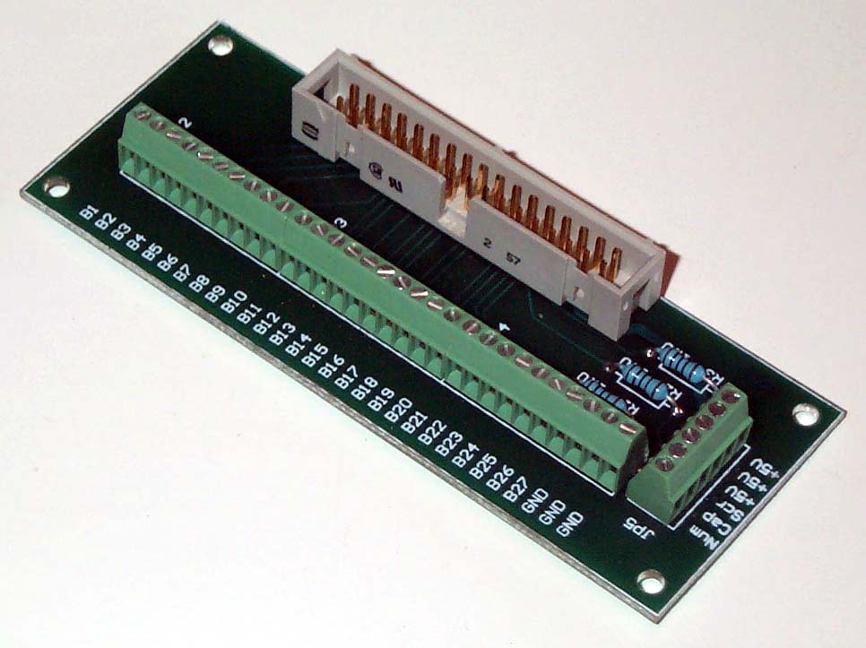 |
This is one of the connector cards, the Direct-card. As you can see it is very simple to build. |
 |
The same card directly from above. Note the three Num, Caps and Scr connectors where you can connect LED's that reflect the state of the Num Lock, Caps Lock and Scroll Lock on the keyboard. |
The "Matrix" connector-card
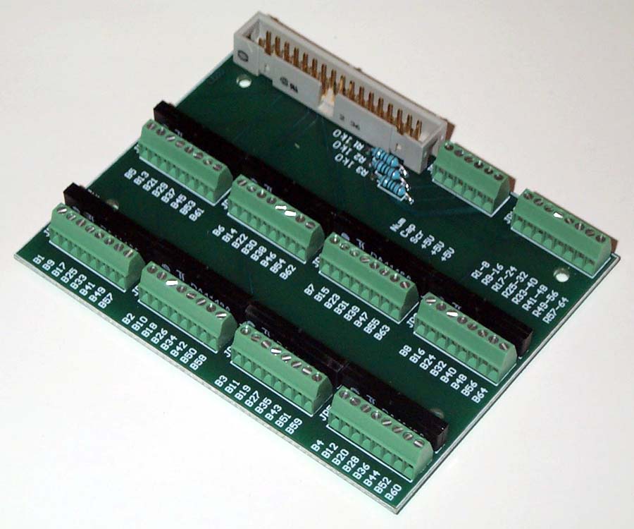 |
This is the other type of connector-card, the Matrix-card. This one is a little more complex (and more expensive) to build, but the advantage is that it can connect up to 64 buttons. Note that this picture has the button-numbers wrong. As of v1.02 of the ButtonBox2 Atmel CPU-code, they should be numbered from top to bottom as shown with red text in the picture below. |
 |
The same card from above. The long black "boxes" are "8-in-one" diode-arrays used to avoid keyboard "masking" and "ghosting". Note that this picture has the button-numbers wrong. As of v1.02 of the ButtonBox2 Atmel CPU- code, they should be numbered from top to bottom as shown with red text. |
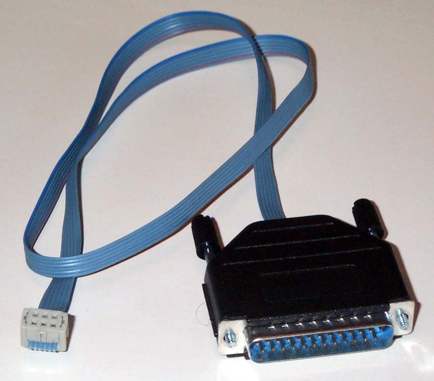 |
This is the cable that is used to update the software in the Atmel AT90S8515 CPU. |
 |
Here is a screen dump of the PC software that can be used to configure the ButtonBox2 (it's the same as the one used for the ButtonBox). |